Right-Angle Glass Pool Gate Latch
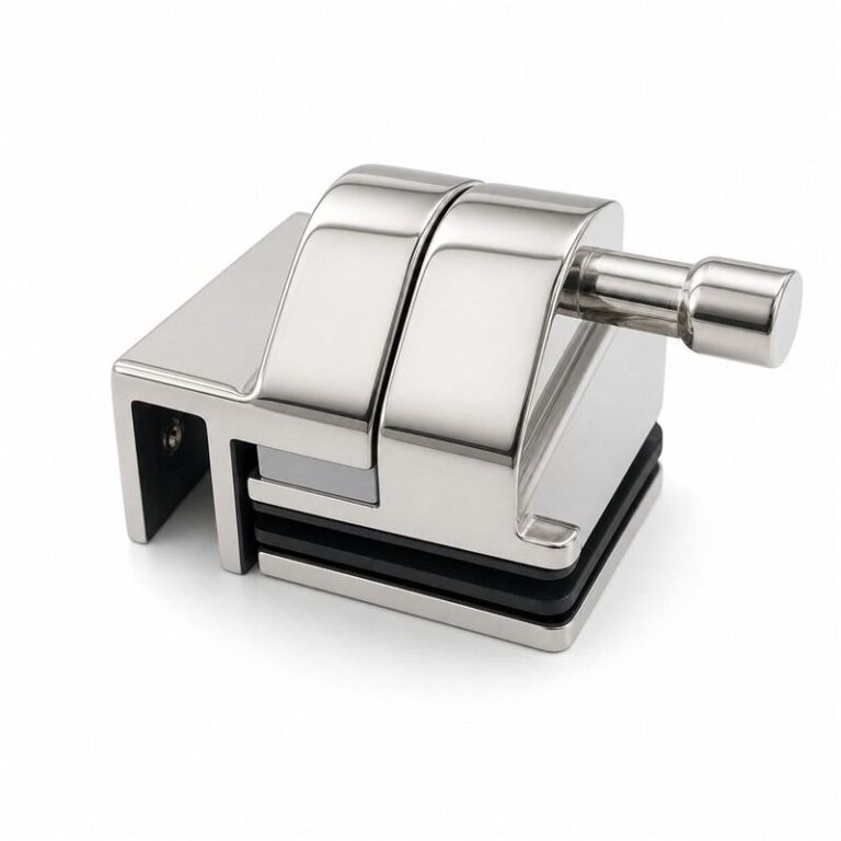
This pool gate latch shows a pull knob, two curved housing covers and right-angle glass attachment brackets. Compare the pictured connection layout...
View Details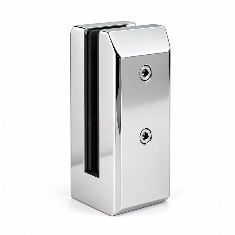
Model: PFH-084 (image reference; model to confirm)
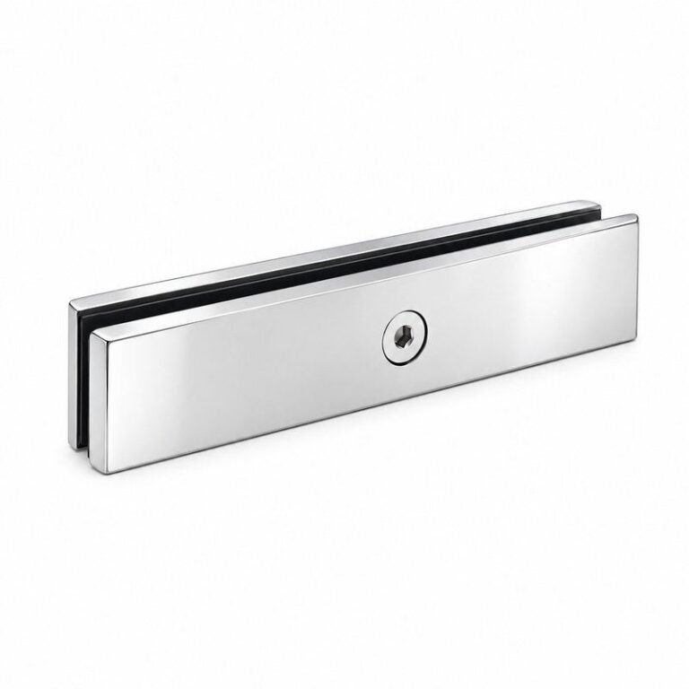
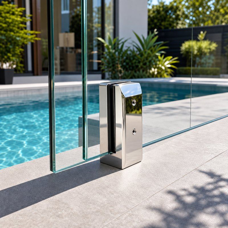
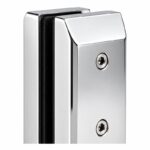
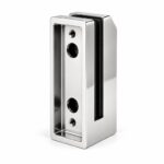
This finish concept shows a square glass clamp body and an extended rear mounting plate with fixing holes. Use the polished silver appearance concept to discuss appearance and project requirements. Confirm the production finish and model specification before ordering.
Product Highlights
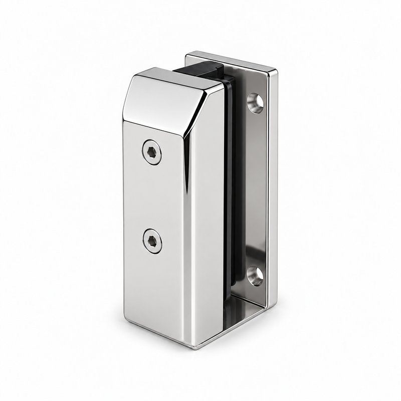
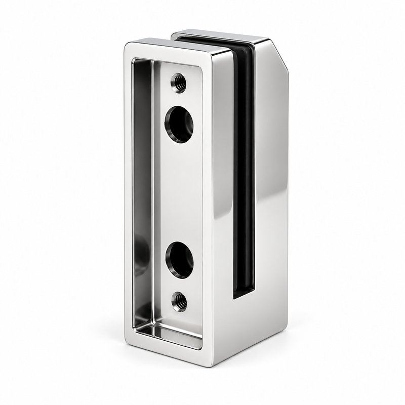
A square glass clamp body and an extended rear mounting plate with fixing holes.
Side mounting plate.
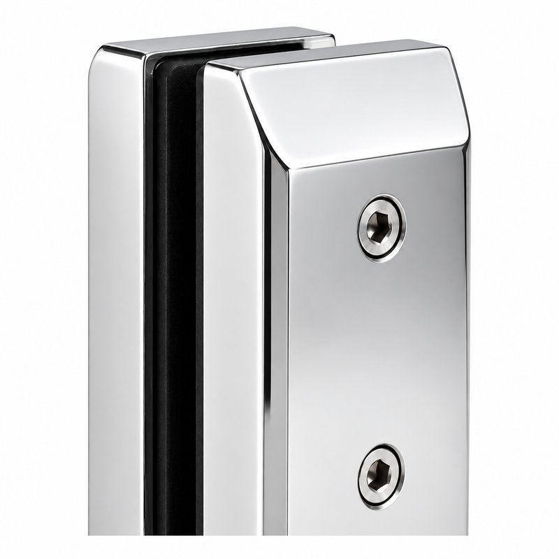
Visible front clamp screw and rear mounting holes.
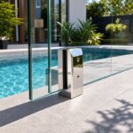
The polished silver side mount glass pool fence spigot concept shows a square glass clamp body and an extended rear mounting plate with fixing holes. This image illustrates polished silver appearance. Confirm the production material and finish against an approved sample.
Use PFH-084 as the image reference when requesting model confirmation. Provide panel dimensions, support spacing, substrate details and the proposed fixing arrangement. Proposed body height: 160 mm; square-body option: 50 x 50 mm. Selection proposal only; not measured dimensions or an installation drawing for this model.
Confirm whether the selected reference uses a base plate, side plate, embedded stem or another fixing method. The visible body shape alone does not establish anchorage requirements. Confirm the complete installation details and the evidence required for the project location before specification.
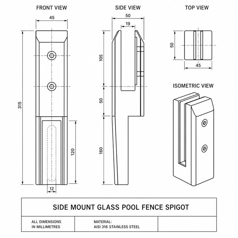
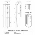
View the reference drawing image for discussion. This reference image is not an approved manufacturing or installation drawing. Request the released dimensional drawing, product specification and applicable installation instructions for the confirmed model.
View source reference drawing (JPG)
Source reference for this catalogue record. This image is not an approved manufacturing or installation drawing. Dimensions and material notes shown on the image are unverified; the selection options listed on this page are separate proposals. Request a model-specific approved drawing before ordering or installation.
Compare the pictured side mounting plate with the project layout. Submit panel dimensions, support spacing, substrate details and the proposed fixing arrangement for model and fit confirmation.
Provide the existing part reference, photographs and measurements of glass slot, body dimensions, base or stem geometry, fixing centres and mounting depth. Confirm compatibility before substituting a component; a similar appearance does not establish interchangeability.
Prepare an itemised schedule with the selected reference, quantities, finish and delivery destination. Confirm the included spigot body, glass-contact liners, covers and the specified fixing components and any project-specific documentation in the quotation.
Send the required changes to glass slot, body dimensions, base or stem geometry, fixing centres and mounting depth, together with the panel layout, quantity and finish reference, for feasibility review. Confirm material, finish, marking and packing requirements in the quotation.
Agree the model drawing, physical sample and included parts before bulk production. Appearance concepts illustrate a proposed finish; production availability requires confirmation.