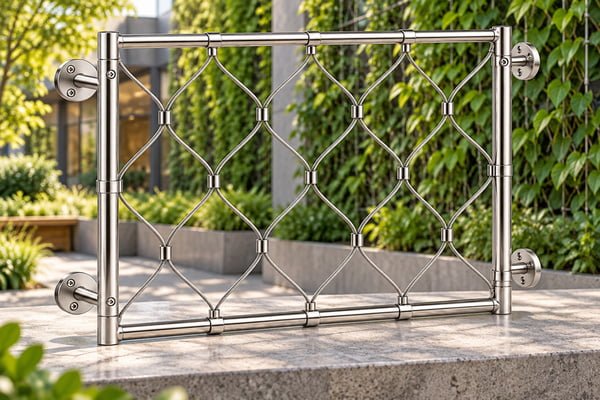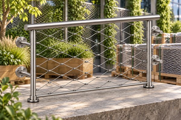
Do not bridge an insulated facade with an improvised long fixing: Green wall cable supports must transfer their loads through an approved connection while maintaining the building envelope’s required performance. Stand-off distance, structural anchorage, insulation, waterproofing and access need coordinated details before procurement.
This interface-review guide is for architects and facade contractors specifying green wall systems. It focuses on responsibility and information exchange. It does not provide a standard anchor length or claim that a catalogue bracket is suitable for every insulated wall.
Draw the wall before choosing the bracket
Prepare a section identifying the structural backing, insulation, membranes, cavities and external finish. Show the proposed support and every layer it crosses. Confirm the actual construction from project records and investigation where necessary; a facade photograph cannot establish the hidden substrate.
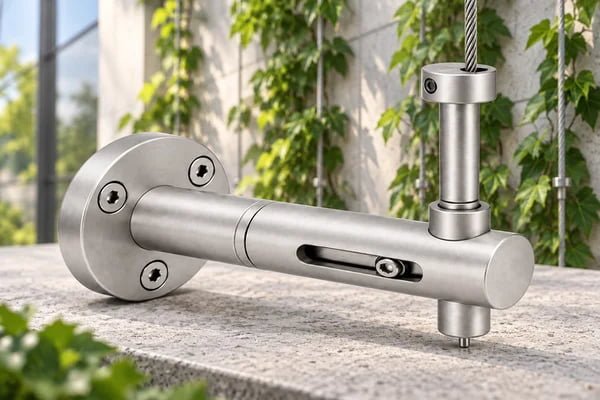
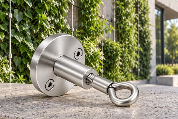
A flange-mounted cable anchor and an adjustable cable support illustrate different interfaces. The facade support checklist helps gather dimensions, but the selected connection still requires project approval. An adjustment slot does not automatically accommodate structural movement or an unsupported projection.
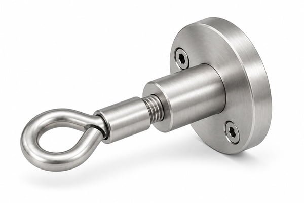
Product reference: Round Flange Eye Cable Anchor — Fine brushed silver appearance. Match the supplied configuration to the approved drawing.
Allocate each decision to an owner
| Interface | Required decision | Typical reviewer |
|---|---|---|
| Structural backing | Load transfer and anchorage | Responsible structural designer |
| Insulation crossing | Support and thermal implications | Facade designer |
| Waterproofing | Penetration and sealing detail | Envelope designer or system supplier |
| Cable connection | Approved fitting and adjustment | Cable-system designer |
| Service access | Inspection and replacement route | Operator and access planner |
Use the table to assign named project roles, not to assume a supplier has accepted every responsibility. Record approval status and the drawing revision beside each interface. A missing reviewer should be resolved before the purchase order becomes the de facto design document.
Understand the significance of stand-off distance
A greater distance between the supported cable and the building can change the action on the connection. In a simplified illustration, a 100 N force acting with a perpendicular 0.2 m lever arm creates a 20 N·m moment. At 0.3 m, the corresponding moment is 30 N·m. These example values explain the relationship only; they are not green-wall design loads or product ratings.
Use the selected manufacturer’s anchor technical documentation for its fixing system. Hilti’s facade bracket information and ventilated-facade engineering overview show that structural and thermal interfaces are coordinated in purpose-designed systems. They do not validate an improvised combination of unrelated parts.
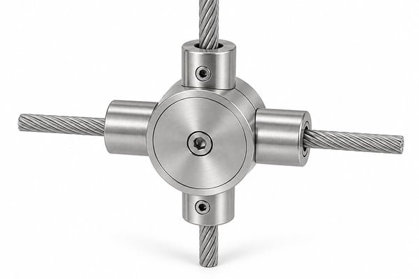
Product reference: Four Way Cable Cross Connector — Silver appearance. Match the supplied configuration to the approved drawing.
Keep insulation and weather protection in the detail
Do not assume soft layers can carry connection forces, or that compressing insulation is an acceptable way to level a bracket. The approved detail must identify the load-bearing elements and how the surrounding layers are treated. Ask the envelope designer to review the completed penetration rather than only the visible exterior bead.
Coordinate drainage, water shedding and future seal inspection. The green-wall construction resource and Jakob greening examples provide application context, while the project’s envelope specification remains controlling. Record any proprietary membrane or sealant requirements from its actual supplier.
Review exposure and material compatibility
Specify cable supports, fasteners and concealed elements individually. Use coastal stainless guidance when assessing exposure and grade-confirmation guidance when defining evidence. Different materials, finishes and adjacent construction can require additional review; do not reduce the schedule to a colour description.
Ask how cleaning reaches the connection once planting matures. Adapt stainless cleaning guidance to the supplied finish and neighbouring materials. The repairable cable-system guide helps organize replaceable sections without implying that a loaded cable can be disconnected casually.
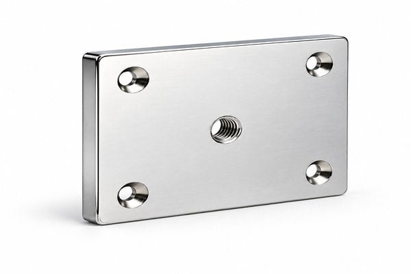
Product reference: Rectangular Threaded Mounting Plate — Polished silver appearance. Match the supplied configuration to the approved drawing.
Release a coordinated sample, then the order
Review a representative connection with the actual wall build-up or an agreed mock-up. Confirm tool access, fitting orientation, cover removal and installation sequence. Photograph the sample and record unresolved issues separately from accepted appearance. A visually attractive sample does not replace structural or envelope approval.
Include approved drawings, component references, quantities and inspection responsibilities in the RFQ. Ask the supplier to identify proposed substitutions before manufacture. If the stand-off changes during design, reopen the connection review rather than treating it as a cosmetic adjustment.
Can one fixing length cover different insulation thicknesses? Only within an explicitly approved arrangement.
Who approves waterproofing? Assign that responsibility to the relevant project professional or proprietary-system supplier.
Review feasible component manufacture through Elim’s capabilities, then submit the coordinated wall sections. A clear interface schedule makes quotations more reliable and prevents unsupported assumptions from reaching site.